![]()
http://www.lsicsi.com/index.htm
<<< LSI/CSI 데이터/응용자료/패키지 치수 자료모음 >>>
LSI/CSI 의 주요 제품
|
LSI Families of ICs |
WESBITE URL |
||||
|
|
|
|
|
|
|
|
Counter ICs - 카운터 |
|||||
|
|
Decade |
- 십진 카운트 |
|
||
|
|
Binary |
- 바이너리 카운트 |
|
||
|
|
Multi-Mode - 다중 모드 |
|
|||
|
|
|
|
|
|
|
|
Divider ICs - 분주기 |
|||||
|
|
50Hz/60Hz Line Frequency - 라인주파수 선택 |
|
|||
|
|
Selectable Six Decade - 선택 가능 6 디케이드 |
|
|||
|
|
|
|
|
|
|
|
Incremental Encoder Interface ICs - 인크리멘틀 엔코더 |
|||||
|
|
Quadrature Decoders - 4 상 디코더 |
|
|||
|
|
Quadrature Counters - 4 상 카운터 |
|
|||
|
|
|
|
|
|
|
|
Lighting Control ICs - 조명제어 |
|||||
|
|
Dimmers, Continuous - 조광기 |
|
|||
|
|
Multi-level - 다중 레벨 |
|
|||
|
|
AGC |
- 자동 이득 조정 |
|
||
|
|
|
|
|
|
|
|
Motor Control ICs - 모터 제어 |
|
||||
|
|
AC Motor Controllers - AC 모터 제어기 |
||||
|
|
Brushless DC Motor Controller - BLDC 모터 제어 |
||||
|
|
Stepper Motor Controller - 스텝모터 제어 |
||||
|
|
|
|
|
|
|
|
PIR Interface ICs - 인체감시(PIR) 센서 |
|||||
|
|
Motion Detector with Triac Interface |
|
|||
|
|
Motion Detector with Relay Interface |
|
|||
|
|
Motion Detector with Latching Relay Interface |
|
|||
|
|
|
|
|
|
|
|
Programmable Digital Lock ICs - 프로그램가능 디지털 자물쇄 |
|||||
|
|
Hardwire Programmable |
|
|||
|
|
Keypad Programmable |
|
|||
|
|
|
|
|
|
|
|
Timers ICs |
|
|
|
||
|
|
Programmable Digital Timers |
|
|||
|
|
Light Activated Timer |
|
|||
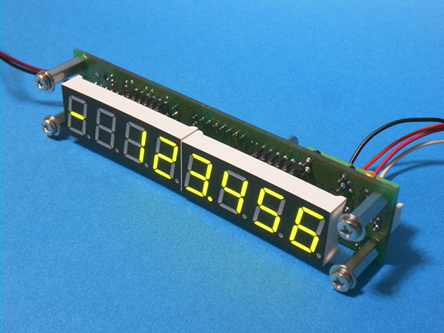
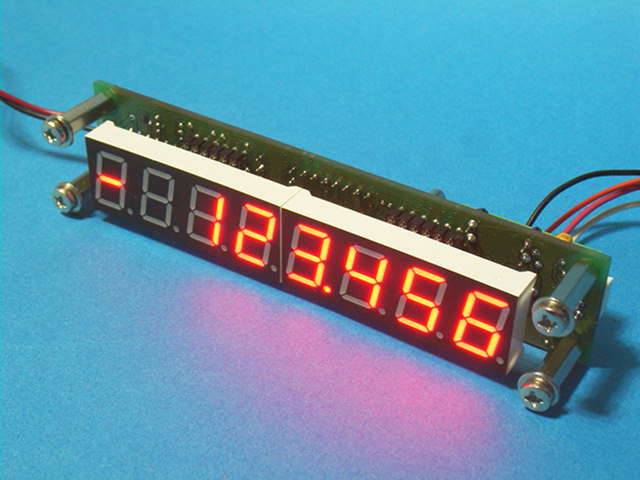
SE-QCNTR-A 카운터
A/B
상 또는 Pulse/Dir 신호 입력
최대 2.5MHz A/B 상 주파수 카운트
진행방향(+/-)
, 소수점 위치, 4 x 쿼더래쳐 모드
디스프레이 유니트 (X1, X2, X5, X10) 기능을 설정
가능합니다.
RS-422 출력형, TTL 출력형 엔코더 사용 가능합니다.
LSI/CSI 사의 고속 카운터 LS7366R 을 사용하였습니다.
DC 5V 로 동작하며 A/B/Index 신호는 RS-422, TTL 레벨 또는 5V CMOS 레벨 입니다.
http://www.robot.kr/se-qcntr-a/index.htm
 |
 |
Linear / Rotary Encoder A B 상 카운터 IC
Quadrature 신호 체배 |
|
엔코더 AB 상신호룰 UP, Down 클록으로 변환합니다. 오실레이터가 내장되어 있으며 출력 펄스폭을 바이어스 저항값에 의하여 결정할 수 있습니다. SN74190, SN74193, CD40193 에 직결하여 사용할 수 있습니다. |
|
LS70183: 8 Pin DIP |
|
|
엔코더 AB 상신호를 CLOCK 신호와 UP/Down 방향신호로 분해합니다. 오실레이터 회로를 내장하고 있으며 클록 펄스폭은 바이어스 저항에 의하여 변화할수 있습니다. CD4516 에 직결하여 사용할 수 있습니다. |
 *
Up
클록 / Down 클록 *
Up
클록 / Down 클록* 출력펄스폭을 200nS~400nS 설정 * 1X, 2X, 4X 체배 * TTL, CMOS 호환 출력 * 3V ~ 5.5V 동작전압 LS70183: 8 Pin DIP |
|
|
| A/B 상 엔코더 카운터 |
24 비트 멀티모드 카운터 입니다. 프로그램에 의하여 여러 가지의 카운터 모드를 설정합니다. 외부 클록이 필요치 않으며 고속 카운트가 가능합니다. 국내의 유명3 차원 측정기(CMM)와 방전 가공기(EDM)의 리니어 스케일 카운터로 오랬동안 사용된 산업 표준 IC 입니다. 8 비트 데이터버스 방식의 프로세서와 연결하여 사용합니다. |
 *
8 Bit 데이터 버스 *
8 Bit 데이터 버스* 프로그램에 의한 멀티모드설정: 1x, 2x, 4x Qudrature Counter Up/Down, Binary, BCD, 24Hour Clock. Divide-by-N * DC 에서 25MHz 까지 카운트 가능 * 24-Bit 비교기로 프리셋 값과 비교 * 상태레지스트 읽기 가능 * CMOS/TTL 입출력 호환 * 3V 부터 5.5V 까지 동작
LS7166: DIP |
|
|
1개의 패키지에 독립적인 24비트 카운터 2 개를 내장하고 있습니다. Quadrature 입력에 디지털 필터를 내장하여 노이즈에 강력한 시스템 설계가 가능합니다. Quadrature 모드에서 17MHz(최대)의 클록이 필요하며 이때 2.2MHz 의 Quadrature 주파수까지 카운트 가능합니다. 8 비트 데이터버스 방식의 프로세서와 연결하여 사용합니다. |
 *
30MHz 카운트 주파수 *
30MHz 카운트 주파수 * 4.3MHz 4x A/B 상 카운트 * 완전 독립된 두개의 24Bit 카운터 * A/B 입력 디지털 필터링 * 필터영역 초과 신호는 Error Flag 발생 * x1, x2, x4 Quadrature 카운터 모드 LS7266R1: 28 Pin DIP |
|
|
서브미크론 이하 정도의 레이져 스케일과 같은 초정밀, 초고속용 Quadrature 카운터 입니다. 9.6MHz 의 Quadrature 신호를 카운트 할 수 있습니다. (5V, 40MHz FCKI) Index 신호에 의하여 카운터 데이터값의 프리셋이 가능합니다. (마이크로프로세서의 인터럽트 기능을 사용하지 않음) SPI 인터페이스를 가진 마이크로 프로세서에 연결하여 사용합니다. |
 *
1x,
2x, 4x Quadrature Counter *
1x,
2x, 4x Quadrature Counter* 32 비트 데이터레지스터, 비교레지스터 * 32 비트 출력레지스터 * Index 펄스에 의한 카운터로드(프리셋) * 8 비트, 16비트, 24비트, 32 비트 동작모드 LS7366R: DIP SPI/MICRPWIRE
|
|
|
|
|
|
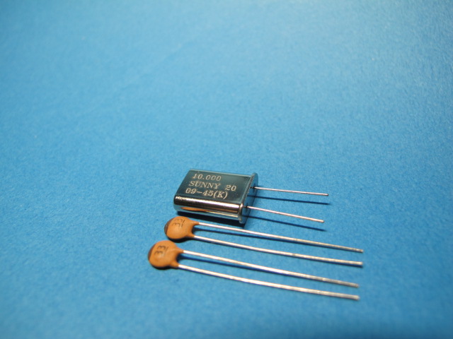
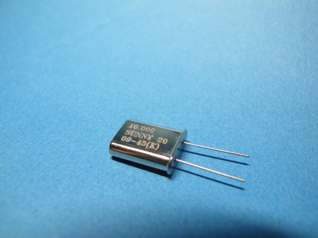
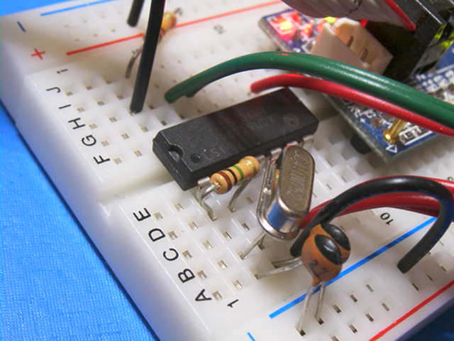
LS7366에는 표준형의 10MHz 크리스털과 33 pF 의 로드 캐패시터를 사용합니다. |
|
LS7366에 크리스털 사용 시 12MHz 이하 주파수를 사용하여야 합니다. 높은 주파수의 크리스털은 발진하지 않습니다. 또한 ATS 형은 주파수에 관계없이 발진하지 않으므로 사용하지 않아야 합니다. 높은 주파수를 원하면 (5V 에서 40MHx) 오실레이터를 사용하거나 CPU 클럭을 사용하시기 바랍니다. |
|
|
|
|
|
|
|
|
|
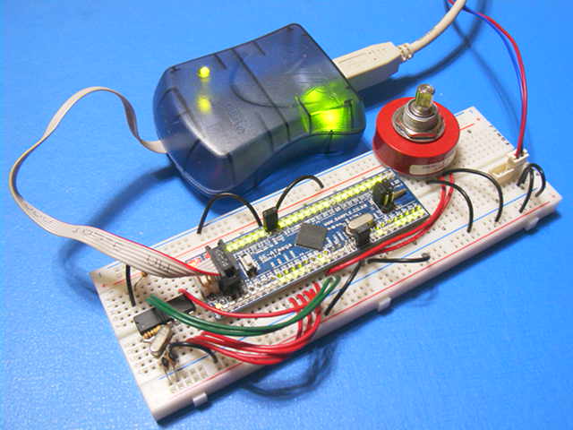
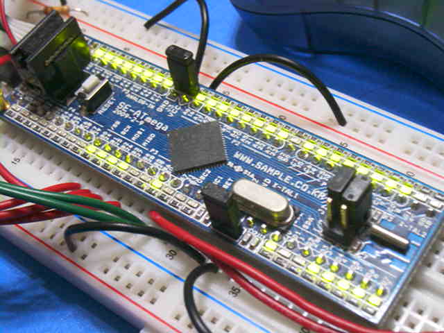
LS7366R 응용예 ( C 소스 프로그램 공개) LS7366R 을 ATMEGA128 에 연결(SPI)한 예입니다. 4 바이트의 카운트 값을 읽어 PORTF, PORTA, PORTC, PORTD 에 디스프레이 합니다. 프로그램 순서입니다. (1) ATMega128 의 초기화: LED를 점등하기 위한 PORT와 SPI관련 포트를 초기화 합니다. 4 바이트의 카운터 값을 LED 로 점등하도록 PORTF, PORTA, PORTC, PORTD 를 출력으로 설정합니다.
DDRF = 0xFF; // Atmega128 의
PortF 를 출력포트로 지정 31 - 24 (MSB)
DDRB = 0x07; // Atmega128 의 PORTB.0 (SS),
PORTB.1(SCK), PORTB.2(MOSI)를 ATmega128 의 SPI 레지스터를 초기화 합니다.
SPCR = 0x53; // SPE와 MSTR 비트를 1 로하고 SPR1,
SPR0 를 1 로 하여 SS를 High 에서 Low SS를 High 에서 Low (4) LS7366R 의 CNTR 레지스터를 0으로 리셋트 합니다. (선택사양) SS를 High 에서 Low LS7366R로 부터 데이터값을 읽습니다. AB 상 신호에 따라 카운트 되는 레지스터는 CNTR 레지스터 입니다. CNTR 레지스터의 값은 CNTR 레지스터를 직접 읽는것은 아니고 OTR레지스터로 복사 (4 바이트 동시 래치)한후 OTR 레지스터를 읽습니다. (5) LS7366R의 CNTR 레지스터값을 OTR 로 복사(래치)합니다. 1 바이트 를 전송합니다. SS를 High 에서 Low (6) OTR 레지스터 읽기 명령으로 1 바이트를 전송하고 4 Byte 의 OTR 레지스터를 읽습니다. SS를 High 에서 Low * SPI 에서는 데이터를 읽기 위하여 어떠한 데이터(여기서 0x00 이며 LS7366R에서 수신 되지만 아무런 의미는 없습니다.)를 SPI 로 보내야 LS7366R로 부터 데이터를 읽을 수 있습니다. (7) 연속해서 읽는 경우 (5),(6)의 과정을 반복합니다.
예제프로그램은 Imagecraft 사의 ICC-AVR 데모버젼을 이용하였습니다. 소스프로그램 다운로드 (ICC-AVR C 컴파일러를 다운받고 압축 해지한 폴더에서 Menu-> project 오픈하면 됩니다.) SE-ATMEGA-M 보드에서 동작하도록 작성되었습니다. Imagecraft ICC AVR V7 데모버젼 다운로드 //ICC-AVR application builder :
2009-08-04 오후 11:03:25 |
1개의 패키지의 4 개의 독립적인 24비트 카운터를 내장하고 있습니다. Quadrature 카운트 모드에서 디지털 필터링 기능이 있습니다. 4.5MHz 의 Quadrature 신호를 카운트 할 수 있습니다. (5V, 20MHz PCK) 8 비트 데이터버스 방식의 프로세서와 연결하여 사용합니다. |
 *
24
Bit 4 Axis Quadrature Counter *
24
Bit 4 Axis Quadrature Counter* x1, x2, x4 Quadrature 모드 LS7566R-TS: TSSOP |
|
|
16비트 / 8 비트 데이터 버스와 1 패키지에 1 축/ 2 축의 4 가지 모델이 있습니다. LS7766DH -> 2 축 16/8 비트 데이터 버스 H 모델은 8 비트 또는 16 비트
데이터버스 방식의 프로세서와 연결하여 사용합니다. |
|
* 1x, 2x, 4x Quadrature 카운트 모드 LS7766DH-TS:
TSSOP
|
|
|
엔코더/카운터 관련 IC는 상시 재고 유지하며
5,000 개 수량 부터 미화표시($) 견적 발행합니다.
DIP
Outline Drawing
SOIC
Outline Drawing
TSSOP Outline Drawing
LSI/CSI 의 홈페이지가 열리지 않을 때 다운 받습니다
<<< LSI/CSI 데이터/응용자료/패키지 치수 자료모음 >>>
가 격
| LSI PART NUMBERS | Data Sheet | 가격 (VAT 별도) |
| LS7183 (Dip) LS7183-S (SOIC) |
A/B Quad to Up/Down | 4,100 원 |
| LS7184 (Dip) LS7184-S (SOIC) |
A/B to CLK/Direction | 4,100 원 |
| LS7166 (20Pin Dip) LS7166-S (20Pin SOIC) LS7166-TS24 (24Pin TSSOP) |
24
Bit Quad. Counter 8 Bit Data Bus |
15,000 원 |
| LS7266R1-D (Dip) LS7266R1-SD (Skinny Dip) |
2
x 24 Bit Quad Counter 8 Bit Data Bus |
19,000 원 |
| LS7266R1-S (SOIC) LS7266R1-TS (TSSOP) |
2
x 24 Bit Quad Counter 8 Bit Data Bus |
18,000 원 |
| LS7366R (Dip) LS7366R-S (SOIC) LS7366R-TS (TSSOP) |
32
Bit Quad. Counter SPI Bus |
5,300 원 |
| LS7566R-TS (TSSOP) | 4 x 24 Bit Quad Counter | 19,000 원 |
| LS7766SO (Dip) LS7766SO-S (SOIC) LS7766SO-TS (TSSOP) |
Quad.
Counter 8 Bit Data Bus |
13,500 원 |
| LS7766SH-TS (TSSOP) | 16 Bit Data Bus | 14,500 원 |
| LS7766DO (Dip) LS7766DO-S (SOIC) LS7766DO-TS (TSSOP) |
Quad.
Counter 8 Bit Data Bus |
15,000 원 |
| LS7766DH-TS (TSSOP) | 16 Bit Data Bus | 16,000 원 |
| LS7290 (Dip) | Stepper Motor Cntr | 3,800 원 |
| LS8297 (Dip) LS8297-S (SOIC) LS8297-TS (TSSOP) |
Stepper Motor Cntr | 5,200 원 |
| LS8297CT (Dip) LS8297CT-S (SOIC) LS8297CT-TS (TSSOP) |
Stepper Motor Cntr | 5,900 원 |
| LS8397 (Dip) | Stepper Motor Cntr | 6,700 원 |
| LS8397-S (SOIC) LS8397-TS (TSSOP) |
Stepper Motor Cntr | 6,500 원 |
 |
||
 *
Up
클록 / Down 클록
*
Up
클록 / Down 클록